- Links to overviews
of WWII
German aircraft compasses. (The WWI compass list is
momentarily not available)
- The Royal
Airforce Museum's own website
also displays
many items with their
data (via Navigator / search : "compass").
Specialized books
: go to Miscellaneous / History and
Bibliography.
A
AERA
AERO-COMPASS
Aéronautique
Militaire
AIR
MINISTRY (A.M.)
AIRPATH
(go
to "Standby compass")
Albatros-Aircraft
ANDREWS
Aperiodic
Compass
Arcaute (see Navigation)
Armee-Kompass
I, II & III
ASKANIA
Astrocompas
AVIARICHTER
|
B
B,
B-3A (Type B)
BADIN
Ballooning
BAMBERG
BARBIER,
BÉNARD,
TURENNE
(B.B.T.)
BARKER, David
Bearing Compass
BENDIX
BÉZU
BOES
BORDÉ
BROWNE
& SON
|
C
CAMPBELL
(Bennett)
CARETTA
Centesimal
compass
CLIFT
COLLINS
COLOMBEL (see DEPERDUSSIN)
COLVIN
Compass Spirit
Compensation
(books)
Consolidated
Instruments
COOK
Cobb-Slater
CREAGH-OSBORNE
(C-O)
|
D
D-12
DALOZ
- DOIGNON
Damping Liquid (Spirit)
Dead Beat
DELSUC
DEPERDUSSIN
De
VRIES
& COURBET
Dordilly (see DALOZ)
DR -
Distant Reading
Compass
Drift
Driftmeter (see DALOZ)
DURKEE
|
E
Earth
Inductor Compass
ELGIN
WATCH CO.
Emil
(German compass type)
F
FAVÉ
FK 5 (P), FK
6 , FK 10, FK 15
Flux Gate or Valve (gyro
compass)
Franz
/ Fränzchen
(German compass type)
Functional Test Device
(VION System)
|
G
GAUJOUR
GAUMONT
GENERAL
ELECTRIC
GOERZ
GROSS
GUERRA
Gyrocompass
/ gyrosyn
|
H
HAMILTON
INSTRUMENTS
HASLER
HEATH
HOLMES
HUGHES
& Son / HUSUN
HUSON (Smith's
~)
|
I
Induction
compass
J
Japanese
Manufacturers (WWII) |
K
KADLEC
K.B.B. (see
Kelvin, B. & B.)
KEARFOTT
KELVIN
&
partners: Bottomley
& Baird (K.B.B.),
K. & J. White, K.
& Hughes
KG-1B
(КГ-1Б in cyrill. letters)
KI-12
/ KI-13
(КИ-12 / КИ-13 in cyrill. letters)
KIRBY-SMITH
KNUDSEN
KOLLSMAN
KRAUSS
|
L
LEPAUTE
Henry
Le Prieur (see Navigation)
Letecke Pristroje Praha
LINDBERGH
Lke 11 E, Lkf 5/6, Lkp 4, Lp5
(Askania)
LUDOLPH
|
M
MAGNESYN
MARQUIS
MAUVE
MAXANT
Mark II (s. Air Ministry)
MONODEP
MOREL
(B.B.T.)
|
N
Navigation
(Navigraph)
NISTRI (go to OMI)
Northerly Turning
Error
O
OMI (Ottica Mecc. Italiana)
|
P
PATIN
Pattern
200, 223,
259
etc.
PDK
/ ПДК
in cyrill. letters
PENTZ
PERCHERON
PEZZANI
0-2
Pfadfinder
für Aviatik
Pinedo's
Compass
PIONEER
(see also BENDIX)
PLATH
Projektionskompass
(PLATH PH 10)
PZO
Polskie Zaklady Optyczne
|
Q - R
Radiation, Radium
Paint
Radio
Compass
R.A.E.
/ R.A.F.
(Royal Aircraft Establishment / Factory)
Repeater
Compass
ROSENFELD
|
S
SALMOIRAGHI
SALZGEBER (s. Star Compass Co.)
SENDTNER
SERPEILLE
SESTREL
SHERMAN
SHERRILL
(land vehicle compass)
SIEMENS
& HALSKE
SKYLEADER
SMITH's
Aircraft
Instruments
SPERRY
Stand-by
Compass
Star Compass Co.
Star Pathfinder (s. Consolidated Insr.)
STOPPANI
Swinging
|
T
Tanks
and Armoured Vehicles
T.A.
103
- THÉDENAT
Tele-compass
TELEOPTIK / T.LK18
TILLANDER
TITTERINGTON
|
U
UGR-4
(YГP-4 in
cyrillic letters)
URFER
|
V
VION
(including
compasses for land vehicles)
|
W
WARBURG
W.D.
32
WHYTE,
THOMSON & Co |
X - Y
- Z
Z9, Z10, Z4h (Plath)
ZÜRN
Unknown
aircraft compasses |

-
A -
AERA
The
Société
Anonyme d'Exploitation et
de
Représentation Aéronautique
(A.E.R.A.) was a
French company located 29, av. de la Grande
Armée, Paris
16
e.
Addresses in Anvers/Antwerp are also known. It supplied
many flight instruments in the 1920s. Its logo featured a
bird (woodpecker). The compass type A.M. 1 has been designed
by Louis Dominique Joseph Armand DUNOYER
(source:
L'Aéronautique, Ausg. 16, Sept. 1920)
who had filed before WWI several patent fpr ship compasses (btw. 1906
and 1909). AERA is also the designer of a famous drift
calculator (link to picture and descr.:
dérivomètre,
patent no. 451.080, 1913) which could be adapted on top of a compass or
a map holder.

Aero-Compass was the designation of the very first compasses
made by Hughes and used
aboard aircraft. They had been designed by Captain
Creagh-Osborne —hence
the engraving C-O. AERO COMPASS (
see
pic at right - courtesy auction website
ViL veryimportantlot.com)— and also called
the Pattern 255-259 depending on the size and use. Later
models were specific for PILOT and OBSERVER (see
entry Creagh-Osborne below)
The very first compasses used aboard French balloons and
aircraft
during WWI and in the 1920s featured in addition to the makers
name the words
AÉRONAUTIQUE MILITAIRE. We know of such compasses made by
MAUVE
and by
VION.
The authority called Aéronautique Militaire was a department
of the War Ministry. These compasses are also part of the U.S.
study called
Report
No. 128 dated 1923.
 |

Click
on the image at
left to see a full description of both compass
types. |

The
Air Ministry
was formerly a
department of the British government with the responsibility of
managing the affairs of the Royal Air Force. It existed
from 1.4.1914 to 1964. Different types of
aircraft compasses were built for the A.M.: the
P Series
compasses were
pilot’s
compasses,
the
O
Series being
observer's
compasses.
During WWII, they were built by several makers. After
the serial number on the bezel, a suffix (letter or sign) denotes
the manufacturer
or another
characteristic. They are explained in
the
Air
Publication 1234. Henry
Hughes and Sons (later Kelvin Hughes)
also made
compasses under the trade name HUSUN.
We
display here just a few examples: The model 06A, a landing compass was
a
hand bearing
compass for use on the ground (for modern instruments see SESTREL,
SAURA).
Other compasses installed on-board of aircraft were based on a same
design like the P series. Some were equiped with a mirror and
the
O2 had an azimuth circle.
The compasses used by the RAF were aperiodic
compasses, i.e. they
settled onto a true course after a turn without overcompensation, this
being achieved by means of sophisticated features like strong magnetic
moment, small inertia and heavy damping. For further information
concerning navigation on RAF aircraft with
these compass types and more technical details concerning the aperiodic
compasses, please go to
cairdpublications.
The following information concerning the various P models' chronology
was sent by a friendly visitor. Any complementary data will be welcome:
 Picture at
right courtesy
M. Goosey:
A P12 compass (click on the image for an enlarged
view).
Picture at
right courtesy
M. Goosey:
A P12 compass (click on the image for an enlarged
view).
- P1: Apparently no compass was ever designated this way. This abbrev.
stands for a former WW1 compass.
- P2 (see table below)
- The P.3 was a
vertical card compass dated about 1930. I suspect (but have no hard
evidence) that the designation P.1 was assigned to WW1 RFC (
Royal Flying
Corps, predecessor of
the RAF) compasses that
remained in service after the Air Ministry was formed.
- The P4 was a mid-1930s compass and was used in
“large” aeroplanes, including the
Hawker
Hart,
Sunderland
and early four-engined bombers. It was replaced by the P10, which was
identical in size but had four cross hairs rather than two. Some P4's
were modified with four cross hairs as P4A. It was the P10 that would
have been fitted to the
Lancaster
rather than the earlier P4, but I have no doubt that P4's were also
used
when the need arose.
-
I have no information about the P5.
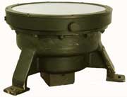
- The P6 was fitted to “small” aeroplanes. It was
replaced by the P8, which had a slightly larger bezel.
- The P7 was an inverted version of the P6 and was replaced by the P9,
which was an inverted P8.
- The P8 was in common use from about 1937 and was used in the
Spitfire, Hurricane,
Tiger Moth,
etc. and was replaced by the P11. There was also a version marked as
the P8M (M for 'Modified with four cross hairs').
- The P9 was an inverted version of the P8 and looked similar to the P7.

-
The P10 was an improved version of the P4 with four cross hairs.
- The P11 was an improved version of the P8 with four cross hairs.
-
The P12 (s. pic. at right) was an inverted version of the P11 viewed
via a mirror which
hung below the bezel
(see
picture). It probably was the
last magnetic compass in the
P Series.
CAUTION
-
RADIATION HAZARD
The
cardinals (N-E-S-W) and the
10-deg. markings on the compasses were made of a radioactive
compound (radium and zinc sulfide/copper) which
is still "hot" although the paint is no longer visible in
the dark. In 50 cm (1 1/2 ft) distance, the gamma radiation measured is
0.35 µSv/hr (microsieverts/hour). The natural background
radiation is about 0.10 µSv/h. The
threshold for hazardous radiation is 0.30, this means that this
instrument is not dangerous if always kept at this safe distance from
the body (10 ft).
Click
on picture for
an enlarged view
DON'T
OPEN
THESE INSTRUMENTS AND NEVER MINGLE WITH RADIOACTIVE PARTS.
DON'T STAY DURING LONG PERIODS NEAR THEM.
YOU WILL FIND MORE DETAILS ABOUT THE RADIUM-PAINT COMPOUND HERE.
The application of Radium compound paint for letters and figures
instruments was described in a
patent no.
110,203
(
follow
link for pic.) filed
in Oct. 1916 by F. O. Creagh-Osborne, F. H. Glew, A. J. Hughes and
Henry Hughes & Son Ltd.
Read the news about
contaminated beaches because of the
dumping of
decommissioned equipement after
WWII.

Pict. Notes on Aero
Compasses and their Adjustment (Air
Pub. 191,
1918)
(For
a drawing of a sectional
view with the parts list ask the museum's curator via the CONTACT
button)
(Click
on images for
enlarged views)
|

Pic. Magnetic
Compass
in Aircraft (Air Pub. 802,
1920). |
Model
name: R.A.F.* Mark II (note:
for
type Mk III go to HUSUN)
Technical Data
- Dim.: 9½ x
5½ x 5½ in. (240 x 140 x 140mm)
- Weight: 4 lb. 10 oz. (2.3 kg)
- Spherical bowl in a cubic case, inside face of inclined glass window
also spherical
(same radius as bowl), the correction magnets were located in the "grip"
- Designer and maker: Royal Aircraft Establishment, Farnborough.
Description
(in a not quite flawless French ☺) published in La boussole
magnétique pour la
navigation aérienne.
by Capt. Creagh-Osborne,
1916.
This system was especially developed
by Dr. Keith
Lukas to overcome the phenomenon
called Northerly
Turning
Error (description
in Air Publ. 802 - ask for
copies).
*
Royal Aircraft Factory,
Farnborough |
|
Pic. Magnetic
Compass
in Aircraft (Air Pub. 802,
1920). Comprehensive description available: ask for
copies |
 Details:
see at
right
Details:
see at
right
(Click
on images for
enlarged views) |
Type
6/18 - Aperiodic
Compass - Mark III
Technical Data:
Inventors: Campbell
& Bennett, England from
1918 onwards until
superseded by the models described below.
- Dim. (height x
dia.): 4½
x 6½ in. (115 x 166 mm)
Printed
onto crew members training poster (see
enlarged view):
"AIR MINISTRY / DIRECTORATE OF TECHNICAL DEVELOPMENT
/ 4-2-26 / AIR DIAGRAM NO 986"
Printed below border: "16604 W.977/13657 4/25 R. & L.
E.2858"
Original photograph
by courtesy of powerhousemuseum post-edited by
Jaypee for COMPASSIPEDIA |
MARK
IIIA Aperiodic Compass
version 1924, HUSUN
Pic.
courtesy History of
Air
Navigation by A.J. Hughes, 1946 |

|
|
PATTERN
Most compasses correspond to a defined "Pattern". See
overview HERE.
LANDING COMPASS
(see definition and
procedure HERE
)
1
- HAND-HELD TYPE 04 and 06
Stores* Ref. 6A / I.248
* see menue Miscell./Terminlology, successor of Pattern 254
|
AIR
PUBLICATION 1275
General description and section view


(Photocopies
of AM compass manuals can be ordered)
* A landing
compass is used to
"swing" the compass installed in the fully equipped aircraft i.e. to
write a table with the deviation values (description in the
Air
Pub. 802, photocopies available). See also BOES below.
(Click
on the pictures for
enlarged views)
|
Technical
Data
- Diam.: 3.8 in. (95 mm)
- Overall length: 9 in. (190 mm)
- Weight: 2 lb. 4 oz. (approx. 1 kg)
- Serial no.: 38899H (H = Hughes)
The Air Ministry logo (see pic. below) was not engraved on all items.
Some
featured only the Army's broad arrow ("crow foot").

The compass card's winged North symbol (mirrored view):

|
TYPE
P. 2
Certain characteristics
like the divisions ring and N-S arrow are maybe evolutions
compared to the Type P.1.
(Click on the images
for
enlarged views)
|
The
system was apparently gimballed like ships compasses.
 Pictures
courtesy
G. Rooney
Pictures
courtesy
G. Rooney
The casing without the divisions ring.
The aircraft's axis (direction of flight) was represented by means of a
long pin located on the casing's side wall opposite to the word AFT.
The card's south-north axis was enhanced by means of an arrow featuring
a letter S at one end and a
letter N in a red triangle at the northern end. The
arrowhead features two bird wings with feathers
like on the
TYPE 06A's card above (click
on link for
pic). |
Technical
Data
Dimensions
- Height: 3 1⁄8
(80mm)
- Dia. (top rim): 6 ½
in. (165mm)
- Dia. (base): 5 ½ in. (140mm)
- Dia. of compass
disc: 2 3⁄8
in (60mm)
Markings: Type
. P.
2 . (with
the three dots!),
AFT, No. 195 D.
The card
already featured the spider leg-shaped damping wires (see also
the
exploded view
of Type P.6).
The card
supplier's
name in the north symbol (stylized fleur de lys) is HUSUN (click
on link for
pic). The center
letters are
masked by the S-N arrow. This is the abbreviated trade name of H.
Hughes & Son Ltd.
|
TYPE
P. 3
Front view (compass)
(Click on the images
for
enlarged views)
|
LH
and RH views:
  Pictures
courtesy
aspentree123
Pictures
courtesy
aspentree123 |
Technical
Data
Compass type: vertical type, free rotating sphere
Dimensions
- Height: 10 in. / 250mm
- Dia. of compass window: 2.25 in. / 55mm
Weight: 3 lb 11 0z. (1.66 kgs.)
Markings
Type P3, S/No. 734 H* and a large letter M in white paint; Stores Ref.
6A/O.224
Materials
- Compass casing: brass; mouting frame: aluminum, grip: wood
|
Type
P4, P6,
P8 compasses
Stores Ref. 6A/O.227, .367 and .726
These compasses had apparently the same shape. Only internal technical
details vary.
P4
top view and exploded view of P6
(Click
on the
images
for
enlarged views)

|
Side
view:


A P4
in
situ in a Lancaster bomber's
cockpit
(Cockpit
picture
by courtesy of www.spitfirespares.com)
For a FOOTAGE
(part 1 of 2) about low-level navigation and compass use click on the
image below:

|
Technical
Data
P4 - Built in (Lancaster?) bombers
- Diameter: 7 ¼
in. (184
mm)
- Weight: 5 lb. 14 oz (approx. 2.5 kg)
- 4 magnets
P6 - Built in ...?
- Diameter: 5 3⁄8
in. (136
mm)
- Weight: 2 lb. 4 oz (approx. 1.2 kg)
- 2 magnets
P8 - Built in Spitfire
- Diameter: 5 3⁄8
in. (136
mm)
- Height: 3 in (77 mm)
- Weight: ... oz (approx. 0,821 kg)
|
TYPE
P4A
|
Side
view of the casing which is shallower than the other models of
the P-Type series
Pictures courtesy
T. Kent
Click on the images
for
enlarged views
|
Technical
Data
Dimensions
- Height: ... mm
- Dia. (top rim): .. mm
- Dia. of compass
disc: 4
in. (100mm)
- Markings: Type P4A
|
AIR
PUBLICATION 1275
General description and section view (above)
 Photocopies
of AM compass manuals
Photocopies
of AM compass manuals
can be ordered
Click
on the images for
enlarged views
|
The
P4
compass was also available in an inverted
overhead panel
version
(click on the image for a view of the aircraft cockpit)

|
A
compass stowed
in
its transit container
 |
Type P7
Stores Ref. 6A/O.430


Pictures
courtesy G. Rooney
(Click
on the images for
enlarged views) |
AIR
PUBLICATION 1275
General description and section view


(Photocopies
of AM compass manuals can be ordered) |
Technical
Data
Type P7 aircraft course-setting compass with illuminated grid and a
mirror in the base to reflect the compass reading.
- Diameter: 5 ½
in.
- Height: 8 in.
- Weight: 4 lbs. 8 ozs. (approx. 2.3 kg)
|
TYPE P.8

|
Side view, simplified crown

Pictures
by courtesy Cl.
Waldteufel
|
 Technical Data Technical Data
- Dia.: 161 mm
- Height: 120 mm
- Weight: 1.021 kg
At r.: A P8 in RAF blue-grey on its container
|
TYPE P.9

|
TYPE
P.9 M
 Pictureby
courtesy M. Goosey
Click on the images
for
enlarged views
Pictureby
courtesy M. Goosey
Click on the images
for
enlarged views
|
TYPE P.10

Picture by courtesy D.
Broughall
|
Type P.11
"Designed
in conjunction with the Admiralty Compass Department and
manufactured by Kelvin & Hughes Ltd."
Description: slightly smaller than the P10.
Type
P.12
See list of compasses above and picture of blue compass at r.
|
OVERHAUL AND REPAIR
INSTRUCTIONS
(full text available for P. 11 and P.12)

|
Fig.
14 - Exploded view
 |
Type O.2 and O.3
with
azimuth circle
Stores Ref. 6A/O.380


Picture
at left courtesy J. Richardson
Pic. at right: O.3 (centesimal
system)
|
AIR
PUBLICATION 1275
General description and section view
(Photocopies
of AM compass manuals can be ordered)
|
Technical
Data
- Dia.: 6 ¼
in.
- Weight: 6 lb. 2 oz. (approx. 3 kg)
Azimuth circle
(stores Ref. 6A/O.411)

Click here for a FOOTAGE
about a compass in perfect condition. |
Type SO2 - Stores
Ref. 6A/1078
Picture
courtesy 28peche
(Click
on the images for
enlarged views) |
Side
view of prism
and lamp
fitting
|
Technical
Data
- Diameter: 16.5 mm
- Weight: ?
Label

|
Bomb
Sight Type D
Stores Ref. 6E/O.276

This instrument is primarily designed for use in the course-setting
bomb sights Mk VII A, B and C.
(Click
on the images for
enlarged views) |
AIR
PUBLICATION 1275
General description and section view
 (Photocopies
of AM compass manuals can be ordered)
(Photocopies
of AM compass manuals can be ordered)
|
Technical
Data
- Diameter: 4 in.
- Weight: 1lb. 11 oz. (approx. 750 gr)
 |

ALBATROS,
Tell-tale Compass
This WWI German Aircraft (see Wikipedia) featured a tell-tale compass (
read description on
enlarged
view of picture at
right courtesy
FLIGHTGLOBAL/Archive online, 1915-0954).
ANDREWS
A system called
ANDREWS
Inverted
Compass
is cited in the U.S. document
Serial
Report no. 1720 -
Experimentation (s. a.
R.A.E.
/
R.A.F.).
We have no picture of it. It can be similar to the Air
Ministry Type
P.4 with mirror.
Aperiodic
Compass
Literally, a compass without a period, that is, a compass that, after
being deflected, returns by one direct movement to its proper reading,
without oscillation. Also known as
Dead
Beat (
link to
a pic of a HUSUN nautical compass). This type of
compass was invented by
G.
R. C. CAMPBELL and his technical
solution implemented in most
Air
Ministry compasses (see
above).
Description published in
Aircraft
and Flying by F.V. Monk and H.T. Winter, Gresham
Publishing Company, London, 1934):
"The "dead-beat" action is attained by making the magnet system very
light (no card is attached to it) and including in it eight radial
filaments. The whole of the remaining space under the glass lid is
filled with spirit and it is the resistance which this liquid offers to
the motion of the filaments which quickly brings the system to
a standstill."
The cardinal points references are placed on four of the filaments. The
azimuth degree marks are
shown on a rotatable verge-ring that carries a set of parallel
grid-lines running in the north and south direction, and the pilot
steers his course by keeping the lines parallel to the long north and
south pointers of the needle system. The verge-ring is previously set
for the desired course by pressing down the ring, turning it till the
degree mark of the course comes against the forward lubber line, and
then releasing (source:
History
of
Air Navigation, by A. J.
Hughes, 1946).
Arcaute
Inventor of a drift assessing instrument called "
estimateur"
- see
NAVIGATION
Armee-Kompass
I, II & III
German WWI compass models built by LUDOLPH and
by PLATH. Go to the relevant entries to these makers.

ASKANIA
German manufacturer (more
information
HERE).
The
confidential three-letter-code during WWII was
bxx
(click on link for pic.).
Pic.
at right: Manufacturer's flyer for gliders compasses.
Click on image for view of the glider compass types Fränzchen
and Kleiner
Emil **
See also Wrist, Marching and Nautical compasses.
Orterkompass (Observer
compass) type
Lkf
5b Franz*
and Lkf 7 Fränzchen**
(Little Franz)
Supply
no. Fl.23203-1,
predecessor model of OK 38
This instrument was also produced by C. Plath and W. Ludolph.
Enlarged
view
of the compass card:
click
on
picture at r.
|

|
Technical data
- Dia.: 120 mm
- Height: 80 mm (case) + 50 mm (glass dome)
- Weight: ca. 750 g (w/o attachment parts)
- Techn. Data in the ASKANIA
catalogue***.

Photographs
and description in the book Luftfahrtnavigation (Sönnichsen, 1940, see
menue Miscell. / History and Bibliography)
|
Type
Lke 6/7 kleiner Emil**
(little
Emil) and
Lke11 Emil*
Note * : During WWI the nickname for pilots was Emil
and for observers Franz.
Source: souvenirs of the WWI
ace Ernst Udet in Mein
Fliegerleben,
1935, and in French translation Ma vie et mes vols,
1955 (no Engl. translation known).
|

Pics from ASKANIA
BORDGERÄTE***, Sonderdruck AERO 510, 1937/38
(flight deck instruments, Special issue)
|
Technical Data
Note ** : The light-weight smaller versions (1/3) of these
Instruments
(made
for gliders and tourism aircraft) bore diminutive designations like kleiner (little) Emil
and Fränzchen
= little Franz.

Photographs
and description in the book Luftfahrtnavigation (Sönnichsen, 1940, see
menue Miscell. / History and Bibliography) |
Großer
Peil-/Orterkompass Lkp 4
(large bearing/observer compass)
|

|
Technical Data
- See ASKANIA BORDGERÄTE
(Sonderdruck AERO 510, 1937/38)
|
Fernkompass
(pneumatic tele compass)

|

Ad. published in 1941
|
 Technical
Data Technical
Data
The assembly comprises the following parts (table: picture of the
catalogue)

At right: functional drawing
See also patent no. 711,582 - 1938/1941
|
Kompensier-Peilscheibe
Lp 5
(compensation bearing disc)

Pictures
courtesy
Jan Hessels |
 |
Technical Data
Link to Description
in the book Luftfahrt-Navigation (Sönnichsen, 1940)
Description in catalogue (click
on image below left)
  |

An astrocompass is not a real (magnetic) compass but an
instrument
used in aircraft like a sextant on ships to determine the
direction of true north and read one's true heading by taking aim at a
celestial body with reference to the data of an almanach. See the
tutorial "Use of an astrocompass" on Youtube:
( https://www.youtube.com/watch?v=P6J5nfflNNY&feature=youtu.be )
A Facebook entry also describes an
inverted
astrocompass.
Joachim Richter was a German watchmaker located Am
Wald 2, Ende Erzbergerstr. 75 Karlsruhe
31. Miscellaneous aeronautical equipment. Automatic watch
Model
08/15 Military (pic.
Maistero/Watch
Lounge).
He also built at least until 1945
pilots'
goggles (pic.
profifilm.de,
mod. 1935).
|
Model FK.16
(Führerkompass
= pilot's compass)
Pictures
Henri Note (click for enlarged views) |

|
Technical
Data
- Weight: 206 gr
- Depth: 60 mm
- Diam 57 mm
The FK16 is a LUDOLPH development and product. It is also integrated in
their navigation equipment for divers.
|

-
B -
This instrument made by SPERRY-BADIN is a
simple compass gyro activated by air flow. Inscription:
"L'appareillage aéronautique" (APA). This company was
created in
1923 and was the successor of the Laboratoire Badin (shop for aircraft
instruments) created in 1911 by the famous inventor Raoul
Badin.
Description and Technical Data: click on picture at right.
In its 1910 catalogue, the French compass maker and
retailer VION displayed two pocket compasses with transparent
glass
bottom, stating that this design was specially conceived for
ballooning.
The other compass (
on
the enlarged
image of the catalogue) was
probably made by
S-L.
See also BORDÉ.
 |

Special compass for ballooning as shown in the VION catalogue
(c. 1910)
Click
on picture above for full descr. |
Technical
Data
- Diameter: 45 mm
- Depth: 12 mm
- Weight:
40 gr
- Manufacturer: Houlliot
- Serial no.: 56 (punched on the side)
It was carried in a leather
pouch with snap lock
and a large round
window. Early
20th
c.
|

Printing plate for catalogues of Houlliot compass retailers
(s. F
S & C) |

Carl Bamberg was a German compass manufacturer located 87-88
Kaiser Allee in
Friedenau
near Berlin. The compasses were installed in aircraft and airships. For
more information click
HERE.
See also Nautical and Pocket Compasses.
At
right: Ad
published in the book
Der
Flugzeugkompass
(Gansberg, 1917)
C. Bamberg developped the first remote
indicating compass called
tele-compass.
"Its liquid magnetic
compass (period of
25 secs.) is mounted in gimbals. A free magnetic element in the form of
a float carries a metal disc cut in shape so as to act as a shutter in
regulating the passage of light projected upwards from the base of the
bowl by two electric lamps diametrically opposite each other. The light
rays from each lamp are focussed by a lens upon a corresponding
photo-electric cell. [...] The cell forms two arms of a Wheatstone
bridge, which includes a galvanometer used as a course
indicator. D.C. is supplied to the bridge. A small deviation
from
the set course unbalances the bridge and is indicated to the pilot by
the deflection of the course indicator hand to the right or
left
as
the plane deviates therefrom" (source:
A. J. Hughes,
History
of Air Navigation, p.
105). Link to
Pictures
(courtesy K. Kracheel,
Flugführungssysteme,
1993).
NOTE: Read full description in English in the relevant
British
patents no. 147,194 and 147,215 (1920).
The original German patents
have not been discovered so far. They were applied for
before
and
during WWI in 1913 and 1917. See
also the modern
system developed by Messrs. Huhn and Kistenich for
model
U-Boats.
The book
Navigation
und Seemannschaft im Seeflugzeug
(Navigation and seamanship for flying boats) by Theo E.
Sönnichsen, 1918, describes the three
versions produced, i.e. the compass as installed in the pilot's or
observer's seat, the overhead
(
tell-tale)
compass installed in the upper wing and the one installed in the lower
wing.
The French company Etablissements
Barbier, Bénard et Turenne (B.B.T.) was
created in 1862 and closed in 1982). It was located 82, rue
Curial,
Paris
19 and was successors of
KRAUSS.
It produced in the 1930's / 1940's compass types
called Type 120,
700 and 900, the models
designed by
MOREL
and also ships compasses together with Doignon (read also the French
Wikipedia). Compass type CR12 Mengden tracker: s. MOREL.
Type
700
- Technical
Data
Dim. (ext. dia. x ht.): ... x ... mm
Photograph of the compass as published in Colonel
Gaujour's instructions
for the compensation
of compasses (1946)
|
 |
Type
120 - Technical
Data
Dim.: ... x ... mm - Patent: see MOREL's "Small compass" type
E10. Photograph of the compass as published in Colonel
Gaujour's instructions for the compensation
of compasses (1946), compare to VION's
Type 150
|
|
|
|
Type
900 - Technical Data
- Dim. (ext. dia. x ht.): 135 x 170 mm

Pictures
courtesy
pseudo17dom |

Photograph of the compass in Colonel
Gaujour's book on compensation
of compasses (1946)
|

David Barker of Greenacres, WA (US) was granted a patent
(no. 104,224) in Aug. 2002 for a head-up display compass
featuring a
mirror-imaged compass rose (
see
pic at right). Read a short description
HERE.
A bearing compass or pelorus is used to measure the angle between an
object the position of which is knwon (church tower) and one's own
position or more specifically the axis of one's
vehicle (read PELORUS in the Nautical Compasses section). It used to be
an important tool to calculate the
compensation
of aircraft compasses with and without bombs.

Bearing compasses made by ASKANIA and PLATH |
Excert : Les
compas d'aviation du Capitaine Gaujour, 1936

NOTE: French designation TAXIMÈTRE, German
designation PEILSCHEIBE
|
Procedure and fig.

|
BENDIX Aviation
Corporation is a U.S. company created in 1928 that merged with
PIONEER.
Inventors like
Adolf
URFER,
G.V. RYLSKY
(see table below) and
Ch.
H. COLVIN filed patents
for Pioneer and Bendix. For more
information go
to "Rockwell Collins" in Wikipedia.

|

Copies of the patents listed on the label are available
|
STRAIGHTFLIGHT,
JR. COMPASS -
TYPE 1802-2B
Technical
data
Dia. (dial):
100mm (5 in)
Manufactured approx. in 1940
Picture
courtesy Ames
Swartsfager - Click
on the images for enlarged views
|
The upper plate masks a lamp.
Pictures
courtesy Tony
KING
(Click for enlarged view) |
Rear face (connectors) |
AIRCRAFT COMPASS
MARK VIII - TYPE 1822
Technical Data
- Breadth: 87mm
- Height: 80mm
- Weight: 883gr
Markings: BU. AERO. U.S. NAVY
F.S.S.C. No.: 33-C-800
MFR'S Part No.: 1822-1-B |
 |
Patent
no. 2,188,821 for a
new system
allowing to uniformly illuminate a compass rose (1938). Rylsky
also filed in 1940 a patent (no. 2.227.368) about the internal
electrical illumination.
(Click
on image at left
for view of full page - Photocopy available) |
Excerpt:
"The novel means of the present invention comprise a transparent ring
of light-conducting material (40) [...] composed of glass, quartz,
"Lucite" or any other suitable material. The light from a lamp
(42) may be introduced in the ends (40c) of the ring and
conducted
thereby around the periphery of the compass. The ring-light is provided
with a plurality of light-reflecting surfaces (fig. 2, 40a and 40b)
extending around the circumference of the ring, the reflecting area of
these surfaces gradually increasing in amount of the distance as the
distance from the light source increases." |
Model
D-12 |
 |
The
patent above was
implemented into the
model
D-12

 |
 |
Cut-away view (Installation instr.) |
 PIONEER
VEHICLE COMPASS PIONEER
VEHICLE COMPASS
TYPE 1829
This compass was used in all sorts of land vehicles
incl. tanks. It is said to have also been used in aircraft
(Installation Instr. avlbl.) but we lack evidence.
Pictures
courtesy priv.
coll.
(Click on images for enlarged views) |
The flight
instrument below is a radio
compass
indicator. It is not a compass per
se but an
indicator that has a needle coupled
to a synchro motor that is coupled (via a 5-wire cable, connector PL
118)
to another device or
mechanism that actually performs the compass function (e.g. flux
valve). The knob labeled VAR
allows the calibrated
direction ring to be set (E-W) for variances in magnetic declination
that is
different at all localities over the world and varies over time
(especially as the airplane proceeds in an East-West direction).
Magnetic variation is noted on maps and aeronautical charts which
allows the pilot or navigator to correct
for this variation as the airplane proceeds from one location to
another.
(This definition was kindly
given by LLoyd Crawford.)

(Click
on the pictures for
enlarged views) |
 |
Radio
compass /
Signal indicator I-82-A
Signal Corps U. S. Army
S/N: 4771
Period: WW2
Technical Data
- Diameter: 13 cm
- Depth: 9 cm
- Weight: 600
gr |

Picture
courtesy worldconflictimages |
 |
The next step was the
integration of the compass into
a complex instrument called Air Position Indicator (ad published
in 1944, Japan is burning...).
(s. KEARFOTT, SIEMENS etc.)
Picture
courtesy worldconflictimages
|

M. Bézu was an inventor who was granted many patent among others for
magnetic compasses and the related devices like flux gates and
repeaters.
He created in 1945 The company called 'établissements BÉZU',
then in 1957 the company 'société d'études et de réalisations
électroniques SERE-BÉZU' which became a subsidiary of SFIM in
1970, then of SAGEM later.
Picture at right: Patent
no. 980.822 (1951)
W. W. BOES Company was a U.S. company located 3801 Salem Ave.
in Dayton, Ohio (created in...? existed until...?).
Products: astrocompass, compass swinging sight (table below).
Click
on the image for an
enlarged view in working position as shown in the original user
instruction |
Instrument
used to perform the operation called SWINGING.
Read more details HERE.
Click here for viewing an ad
dated Sept, 1943.
|
Technical
Data
- Diameter: ?
- Depth: ?
- Weight: ?
- Supply designation and no. :
Sight, compass swinging, 42013536 |

Paul Alphonse Barthélémy BORDÉ (b. 4.4.1872; d.
12.12.1942)
was a French engineer, airship pilot and optician. The company
created by his father in 1856 was located 99, Bd. Haussmann in
Paris.
The engraving on the compasses: Breveté SGDG
(standard French patent mention = see Miscell. / Terminol. / Abbrev.)
refers to the
patent no. 427.490 filed in 1911
for a compass with a course and a drift pointer.
The instruments displayed in the first row were probably
prototypes specially manufactured for filing the patent. They were kept
by the inventor's heirs together with several other compasses maybe
made by wholesale makers. Several versions of the
rotating card are known (s. below).
Pic. at right: Ad published in
the
list of participants in the 1910 world
fair in Brussels (click on image for view of products scope)
- C
CAMPBELL
George Richard Colin
CAMPBELL,
Lieutenant-Commander Royal
Navy filed together with Prof. Geoffrey
Thomas Bennett, both members of the Admiralty Compass
Observatory / Compass Department in 1918 a patent (no. 127,135 -
copies
available) the principle of
which was applied in almost all
compasses
produced for the Royal Air Force (s. the
Air Ministry
models): a double cross of eight wires allowing an optimum damping of
the
magnet needle's oscillations in the fluid. These compasses were called
aperiodic.
He had also filed together with Geoffrey Brancker HARRISON
(Commander, Royal Navy) another patent for a stabilized
compass (no. 125,791) with a solution for the northerly
turning
error problem.
The aperiodical compass designed by Campbell & Bennett
|

Fig. and description
(excerpt of Report
No. 128)
Click
on images for full
view and text |
|

Fig. published in the Campbell-Harrison patent no. 125.791
|
Centesimal
Compass
Special compass developed by
Hughes
& Son.
Several instruments
featuring this very unusual (and short-lived) gradation
(link to
comprehensive
description) are known: the
types O.3
and Pattern 253 A.C. (
Aperiodic
Centesimal). They were
described among others in the
FLIGHT
review, issue July 25, 1929.
A WWII
Japanese
compass also features
the four wires numbered 0-1-2-3 but the
dial is a conventional one.

Picture courtesy T. Marett |
Pic.
published in The Aircraft Engineers' Handbook by R. W. Sloley, sixth
ed.
1953) |
Pic.
published in Aerial Navigation by A. J. Hughes, 2nd ed., p.10 &
11, courtesy Muzeum Lotnictwa Polskiego (Museum of Poland's
Aviation) |

Pic.
published in Aerial Navigation by A. J. Hughes, 1st ed. 1923, p.15
|
CLIFT
Eric Hollocoombe CLIFT (51, Sinclair Road Kensington W.,
London -
born 28.9.1874, d. 22.11.1922,
read
full data record
HERE)
was an engineer. He filed a patent
(prov. spec. 13,203 / no. 3404/1911) for a compass system featuring a
device allowing to mark a course and a transparent bottom to follow the
drift while looking at the ground (compare to the French DALOZ
system). Compasses designed by E. H. Clift and produced by H. Hughes
& S.
|
|
|
|
Technical
Data
Click on the thumbnail
images at left to view
large-size
pictures and read full
description on the National
Maritime Museum's
web site (Royal Museums Greenwich).
Drawings below courtesy Flightglobal
/ Archive (online). |
|
|
|

Shock-mount described in the patent
|

Figs. of the patent
Click
on images at left
for
full
view of the FLIGHT MAGAZINE articles
|
See Rockwell
Collins in Wikipedia - Products: radiocompass, compass slave
indicator
Charles H. Colvin filed in 1920 a first patent (no.
1,334,273) for a compass that could be simultaneously read
from either side and the top so that pilot and observer could use the
same instrument even if not seated
at the same level. He was in 1922
assignor
to PIONEER when he filed a
second patent accepted in 1928. This compass is almost identical to
Hughes' HUSUM model below.
Figures
on patent (photocopy available)

|
Announcement
published in a patents
review

Click
on images for full
view and text |
Figures
on patent no.
1,679,764

|

Official
Air
Publications
published by the british Air Ministry:
-
Notes
on Aero-compasses and
their adjustment (Air publ.
157,
London
1918)
-
Remarks
on compasses in
aircraft by F. Creagh-Osborne
(Air
Publication 802, London Nov. 1920)
Compass types dealt with: Patterns 253, 256, 259, 5/17, 6/18 and R.A.F.
Mark II.
For similar books in
French
go
to Creagh-Osborne (below) and via the
menue point Miscell. / History & Bibliogr. / Early days of
Aeronautics:
Les
compas d'aviation
- Cours
élémentaire de compensation et d'emploi
by Capitaine
Gaujour, 1936,
dealing with the compass types
AERA,
MOREL and
VION.
BBT-compasses
are dealt with in the 2nd issue
published in 1946.
You will also find there a
German
publ.:
Der
Flugzeugkompass,
Kompensieren und Handhabung
(Ganzberg, 1917).
CONSOLIDATED
INSTRUMENTS Co.
The U.S. manufacturer
Consolidated
Instruments Co. of America Inc.
(located at two different addresses in N.Y. city in 1928 and 1929, see
ads below) built in the late 1920's a spherical compass called
Star Pathfinder Type F and P.
The
company's logo was a bird's wing.
Apparently this compass type is a further development of the instrument
patented by Gustave A. Salzgeber and made by the
Star Compass Company.
|
|
(Click
on the images for enlarged views) |
Technical
Data
- Dimensions (ht. x br. x dp.): 6½ x 4¼ x
3¼ in.
(163 x 106 x 80mm)
- Weight: 2 lbs 8 ozs (approx. 1.250 kg)
- The front plate was available with two different shapes: Type F and P
(Pics
at left courtesy fsplanet.com, ads in Popular Aviation magazine 1928
and AeroDigest 1929) |
Ads
(1928/1929)
 
(Click
on images above
for
more ads)
|
WWII ace Flight Lt. Harry COOK designed a special compass for
sailplanes and described it thouroughly in the December 1956 issue of
Sailplane
& Gliding (3 pages).

|
Click
on images for
enlarged views |
Technical Data
This compass type was designed to avoid specific problems arousing when
the fluid kept turning in the bowl after the plane circled in thermals.
The first version was not gimballed. The indicator is a dart pointing
to a divided circle on which E and W are swapped, indicating thus
directly the heading.
Manufacturer: COBB-SLATER Instruments Co. Ltd (acquired in 2007 by BNL)
|
Captain Frank Osborne Creagh-Osborne (1867/1943) was
Superintendent of Compasses at the
Admiralty
and a British inventor. He developed several compass systems which were
manufactured
by
H.
Hughes & Son Ltd, Dent & Co & Johnson Ltd and
also by Sperry Gyroscopes and wrote several books about the development
and use of aerocompasses (see
also the sections Marching Compasses and Wrist Compasses). In
1915,
Henry
A. Hughes
took part in a meeting at the Admiralty and explained
the advantages of this compass (source: minutes of meeting in '
Improvements
in prismatic compasses with
special reference to the Creagh-Osborne patent compass'
-
Ask for a copy). The application of Radium-compound paint for
letters and figures instruments was described in a
patent
no.
110,203
(
follow
link for pic.) filed
in Oct. 1916 by F. O. Creagh-Osborne, F. H. Glew, A. J. Hughes and
Henry Hughes & Son Ltd.
Creagh-Osborne published in 1915 the booklet
The
magnetic Compass in Aircraft)
. He described therein not only
the Pattern 200 but also the compasses utilised by the observer, i.e.
attached to his wrist (or leg) by a leather strap and in Kite balloons
(see menue Miscell. / History & Bibliography - copies
available).
According to Ellis Island's immigration records, he landed in
New
York on June 8, 1918 on board a ship called
Olympic
arriving from Southampton.
The compass made by KELVIN
(link to pic. of
Pattern 200)
was also designed by Cptn
Creagh-Osborne.
- D -
Gaston-Jules DALOZ (living in Ramerupt,
Aube,
France) filed in Aug. 1910
a patent (no. 419.682) for a system that permitted to follow
the
displacement of the landscape on ground through the transparent card of
a compass (see detailed
description
and comment as published in
FLIGHT
no. 107, iss. Jan. 14, 1911). The parallel lines were introduced via an
additional patent in Nov. 1910.
The device was then further developed by Abel-Louis DOIGNON*
(patent no. 431.275, May 1911) who added a liquid damping and
mechanical solutions permitting a rapid (re-)setting.
In spite of this, the compass was not to be used as such (no cardinals)
and the pilot needed a navigation compass. The system was first applied
in 1920 by Le Prieur (
cinémo-dérivomètre
S.T.Aé.) who invented
later the
Navigraphe
(see
Navigation) and also
adapted as a drift assessing instrument and
called
dérivomètre Dordilly
(L'Aéronautique no. 93, Feb. 1927, p. 53) and
dérivomètre Salmoiraghi
(L'Aérospatiale no. 215, April 1937, p. 51).
* See Doignon's marching compass.

The original Daloz-Patent
(Cover 9 2/4" x 1 ft) |
Original drawing of DALOZ's system
|
Version with grid (in Les merveilles de la
science,
chap. Aérostation Aviation by Max de
Nansouty,
Boivin ed., 1911)
|

The further development
(DOIGNON's patent)
|

The oscillations of a compass card are damped by a liquid, generally
destilled water and a small percentage of pure alcohol to avoid
freezing. During WWII the RAF maintenance shops were supplied with such
bottles.
They
were and transported in a
wooden container filled with damping wood chips. These box
and bottles were
supplied by Kelvin-Hughes (s. marking on label: Maker K-H) but with no
Part No. (NIL).
Technical data - Bottle: Ø 95mm, 240mm long,
content designation 6B/373 Compass Spirit, Qty 1
quart. Container size: 360 x 340 x 210mm; total weight: 15 pounds.
Supply
markings (labels on container) : 6B/373 Compass Spirit and
6/Stores/36356/CB.41B.
NOTE: This item is for sale. See more pics in the SHOP.
Jacques
Jules-Marie DELSUC was a French engineer who is considered
as the
main inventor of the gyroscopic compass. He filed several patents
between 1938 et 1947. His system was called
Carpentier-Delsuc
(in
Col.
Gaujour's
book)
because it was built in the plant Ateliers (Jules) Carpentier, 20, rue
Delambre à Paris. List of French patents: 794.310,
810.985,
847.055,
921.822. US patent :
2.247.288
(
copies
available).
Deperdussin was a French aircraft manufacturer (see
Wikipedia) located 19, rue
des Entrepreneurs, Paris.
This instrument with a very unusual design was invented in
1912 by Gaston Emile Colombel who lived 50, rue de
Moscou, Paris (Frebnch patent no. 427.928, 17 Aug. 1911, British pat.
no. 26,282). It was
installed in the following aircraft during the first crossings
of the Channel, three of them in thick
fog: Biélovucie flying a
Hanriot machine, Moineau
flying a
Bréguet,
Prévost a
Deperdussin,
Guillaux a
Clément).
The brochure & catalogue (13 p.,
photocopy available on
request)
also contains exerpts of letters sent by pilots after winning races:
- Crossing of the Alpes by Biélovucie in 1913.
- Coupe Pommery (1,129 km) won by Guillaux in April
1913.
- Races Paris-Amiens-Paris and
Circuit
Forézien
(400 km) won by Molla. The latter flew the best time on the
1st leg of the waterplane race from St. Malo to Jersey and
return in thick fog
(
letter
dated Feb.1913).
A. Védrines thanked the inventor Colombel in the name of
Serbian Air Force pilots.
Model MONODEP 1912
Dampening of vibrations by means of springs.
The
Monodep in the Report
No. 128 dated 1923
(read descr. in the enlarged view)
|
Model MONODEP 1914
Gimballed item, scale
with MILS divisions
(1/4 of full circle = 1600)
(Click
on images for enlargement) |
Technical Data - (Functional
description / patent's fig.)*
The compass magnets are concealed in the bowl. The visible card rotates
in a vertical
plane and is linked to the magnets via a right-angle gear. Only the
cardinals are
painted on the card (red star for North).
The route to be flown is set on the external scale (graduated
90° or 1600 MILS for a full circle) by means of an
arm linked through the cover glass via a 1:4
gear to a second arm terminated by a red star which indicates the
position of the card's north red star. A full circle of the scale
corresponds thus with only a 1/4 of the card's rotation. The heading
measured on a map is set via a special protractor and the external arm
on the scale. The pilot only has to make sure that the two red
stars remain superimposed.
Model 1914 featured an integrated lighting with a battery which
could be replaced in flight (6 hrs life time). The card was
divided into four quarters of different colours and called Capitaine
ROISIN after its designer.
The magnetic declination could be set during production.! This seems
surprising now but in those days, the aircraft range was not big enough
to make an in-flight adjustment
necessary.
* The patent describes a flat instrument. |
Jacques De Vries et Courbet, 17 rue des Pruniers, Paris, was
a
French manufacturer of photographical equipement.
|
|
Technical Data
Dia.: ... mm
Height: ... mm
Click on image at left to read the complete description (excerpt of the
document Report
N° 128, 1923)
|

Click
on the image above for an enlarged
view of the cover |

D.R. - Distant Reading Compass
The DRC system consisted of a gyro magnetic
master unit situated at the rear of the aircraft well away from
magnetic disturbances.
Repeater
indicators were fitted for the
navigator and pilot. Additionally, courses were fed to the Air and
Ground Position Indicators (GPI), the H2S and Mk XIV bombsight. We used
true courses, a Variation Setting Control (VSC) providing the necessary
conversion. The DRC was a reliable, accurate and stable instrument.
Available to the pilot, however, in case of a rare unserviceability,
and a cross-check for the DRC was the
P12
magnetic compass.
- Picture: A.J. Hughes,
History
of Air Navigation, 1946)
Drift occurs when a lateral wind pushes an aircraft sideways off the
desired track. To keep flying along the right course, the pilot must
counteract this drift by steering his aircraft according to a computed
corrective angle. A. J. Hughes writes (in his
History
of Air Navigation) 'one of the
first books on air navigation was a little primer by Cdr Newton, givig
tables of corection for drift'. Some early compasses and other devices
featured a
transparent bottom and a lens with parallel lines.
A. J. Hughes writes in his
History
of Air Navigation (1946, p. 32)
about
one compass "pattern with a very big bowl [that had] a glass bottom
through which the drift over land could be observed by a setting
pointer on the compass float".
He was probably mentioning
DALOZ'
invention or some improvement of it.

DURKEE Co. was a New Yorker ships compass maker. He is named
as the manufacturer of a compass called Type A
featuring a vertical
card. It is described in the Air Service Information Circular dated
June 15, 1920 'Aerial Navigation Instructions', Chapter II.6. (click on
image at right for description)
- E -
This navigation aid was invented in 1912 by Donald M. Bliss (read
Wikipedia) and improved and patented in 1924 by Morris Titterington,
founder of PIONEER Co. This compass type equipped the
Spirit
of St. Louis when Charles
Lindbergh flew from New York to Paris in 1927.
Short techn. descr. in Engl.: see Wikipedia. Exhaustive descr. in
French HERE:
Aviatechno.
(Link :
Views
of components)
Major U.S. watch maker. Incorporated August 1864, sold in
1968. During World War II, all civilian manufacturing was halted and
the company moved into the defense industry, manufacturing military
watches, chronometers, fuses for artillery shells, altimeters and other
aircraft instruments and sapphire bearings used for aiming
cannons.
(Source
Wikipedia)
The B-3A compass was a
later version of the “
Type
B”
compass introduced in
World War I. Most of the production of this particular model occurred
around 1929. Very few of these would still have been in use by the WWII
timeframe. They were one of the most common forms of military aircraft
instrumentation as they could be used in just about any aircraft type
ranging from trainers to pursuit (i.e. fighters) and bombers.
(Source Smithsonian
Institution)

Front
side
|

Rear
side
|
B-3A
Compare with Creagh-Osborne's Pattern 259 and 5/17
design.
Markings: Air Compass A.C. U.S. Army, Type B-3A made by the Elgin
National Watch Company.
Pictures
courtesy P. Grace
|
- F -
Louis Favé (1853-1922) was a French engineer
laureate
of the elite highschool Polytechnique.
He invented many precision instruments.
|
|
Technical Data
Compass for balloons
Interior dia.: 178 mm
Height: 100 mm
|
Descr. excerpt of the
document Report
N° 128
|
Click
on the images for enlarged
views |
Functional
Test Device
This device was made by the French compass
manufacturer
VION to test their own
compasses and used as early as in the 1920s. The wording of the maximum
admissible error in the
test procedure
(see
img. in table centre) was used in a booklet published in
1922 (
Traité
Pratique de Navigation Aérienne,
link to image).
When a
vessel or aircraft makes a turn, the compass bowl rotates and the
liquid inside also. Although the compass disc inside tends to remain in
the same position in space due to the magnets being
attracted by Earth's magnetic North pole, it is
partly dragged (in French
ENTRAÎNEMENT) by the fluid's motion.
With this test one measured how important the drag was. The angular
difference from the
original position after a full (360°) revolution effected in
30
sec. was not allowed to exceed a certain value depending on
the type of
compass shape (here "horizontal" display i.e. flat disc
viewed from
above or
"vertical" display like a sphere, band etc. viewed from a side window)
or size (see below).
Note: The crank needs to be turned about 15-16 times at the rate of 2
sec/turn to make the large disc fulfill a complete rotation in 30 sec.
For the
same amount of crank turns, the small disc only rotates 180°, hence one
needs to operate the crank about 35 times at the rate of 1 turn per
sec. to reach 360° in 30 sec.
In the booklet, it also says that the compass rose
should come back
to its
original position after 25 sec. and 3 to 4 oscillations.
Compass
Testing Device


The large disc is rotated by the crank on the right. The small disc
is moved by a belt
The zero references are the brass pointers to be observed
either from above or from the side.
(Click
on the images for enlarged views) |
Technical Data
Dimensions:
Ø large disc: 277 mm
Ø small disc: 80 mm
Interaxes distance: 250 mm.
Ground plate: 255 mm x 500 mm
Test procedure / max. values
(see translation at right):

Pictures
by courtesy of D. Binon
|
 Excerpt
of the Traité de
Navigation Aérienne (p. 8):
Excerpt
of the Traité de
Navigation Aérienne (p. 8):

DISC DRAG ERROR
After a full revolution effected in 30 sec.
- Max. error 12° on horizontal* compass disc Ø 140 mm
- Max. error 8° on horizontal compass disc Ø 85-75 and 60 mm
- Max. error 7° on vertical* compass disc Ø 60 mm
* Examples of VION compasses with horizontal and vertical disc:

|

-
G -
GAUMONT
The French
Société
des
Établissements GAUMONT,
12 rue Carducci, Paris, patented after WWI
two compass-related systems.
One for an improved
telecompass
working with ring magnets (French patent no. 549188, British
no. 180684, click on the fig.
at right for full-view of the four figs) and another one for a
gyrocompass.
The early U.S. aircraft compasses were quite often adaptions
of the British Creagh-Osborne designs.
Read descr. (excerpt of
Report no. 128) on enlarged view
of picture at
right.
Carl Paul GOERZ Optische Anstalt was a German maker
located in Berlin-Friedenau. Read the company's history in the
German WIKIPEDIA.
In the book
Der
Flugzeugkompass
by
captn.
Fritz Gansberg, 1917 is a description and user instr. of the two
versions below
(copy
available).
S. a. GOERZ pocket and survey compasses.
|
|
Technical
Data
- Dim.: ?
Click
on images for enlarged
views
|
|
Technical
Data
- Dim.: ?
|

Alexander Gross was a Hungarian immigrant who fournded the
firm Geographia in London which produced maps.
He designed an anti-drift aero-compass described in FLIGHT
(Sept. 13, 1913)
and in
The
Mastery of the Air
by Wm J. Claxton (1930).
GUERRA
Udo Guerra was an Italian engineer (dom. 16, Via Stazione S.,
Pietro, Rome, Italy) who invented in 1933 a
tele-compass
(patent accepted in 1935, UK no. 435,437, US no. 2,038,787)
title:
Improvements in Variable Induction Compass with Potentiometric Control
and Indicator.
This
system was the immediate forerunner, if indeed not the direct
inspiration, of the first fixed magnetic element A.C. excited type
compass. The latter was invented by Guerra's associate Ettore Caretta
two years later (Brit. patent no. 451,850. In this radical invention
the determination of the earth's field in the horizontal plane is
obtained without any moving parts at all but by the action of the
current induced as a result of the presence of the magnetic field.
(source: A. J. Hughes,
History
of Air Navigation, 1946, p.
108). Check
also the table showing the separate
development
of Tele- and Repeater compasses
(source: ibid. p. 106).

A gyroscopic compass is an electrically
operated
instrument, controlled and damped either by gravity of electrically so
that the spin axis settles in the meridian. These instruments are not
the object of this museum. The gyrosyn is a remote-indicating compass
system employing a directional gyroscope which is monitored by and
synchronized with signal from an element fixed in azimuth and designed
to sense its angular displacement from the earth's magnetic meridian.
This element, called
flux valve or flux gate (
link to descr. and diagramm),
is
located at some remote
point, e.g.
wing tips, away from
extraneous magnetic influences.
(Source: Chambers
Dictionary of Science and Technology, 1974).
The development of gyroscopic compasses is best described in A. J.
Hughes' Book
History of Air
Navigation
(1946), see ex. picture at right.
For pictures of a modern flux gate
CLICK
HERE.
- H -
Leslie Alfred HAMILTON (1919-2005) created this company in...
to produce and sell his invention, a compass with vertical card. The
designation HI-400 stands for Hamilton Instruments, 4th prototype (read
more details
HERE).
Note:
This system and this company
are not associated with
Hamilton Standard, a
U.S. Company created in the 1920's by Thomas Foster Hamilton (July 28,
1894
– August 12, 1969) who was a pioneering aviator and the
founder
of this company.
This compass type is still being made by
Precision
Aviation. The mechanism is
explained in the
patent
figures.

Click
on the picture for
an enlarged view |
 |
Technical
Data
- Dimensions: 70 x 60 x 50 mm
- Weight: 270 gr/0.6 lbs.
 The
deviation
can be compensated in order to show a correct display by turning the
screws at the lower front part: The
deviation
can be compensated in order to show a correct display by turning the
screws at the lower front part:
the left-hand screw (green paint mark, upper one on pic. below) is for
the North-South axis and the one on the right
(painted yellow) is for the East-West axis. |
HASLER A.G. successor of
Telegraphen-Werkstätte von G.
HASLER, Berne / Switzerland (only information available found in the
International
Guide, imprimerie
Crété,
1931, page. VIII.35)
This company
published
an ad in the booklet The
Magnetic Compass in Aircraft by Captain Creagh-Osborne (1915). Link:
example of a Heath compass.
HOLMES
Edward Lowther Holmes (38, Woodville Gardens, Barkingside,
County of Essex, USA) filed together with Hughes (read below) a patent
accepted in 1942 (US no. 543,069, title
Improvements in and relating to Magnetic Compasses)
describing a system called
tele-compass
featuring an external trailer (link to system's description). He later
developped improved systems called Mag-Gyro and
Repeater Compass
(source: A. J. Hughes,
History
of Air Navigation, 1946).
Check
also the table showing the separate
development
of Tele- and Repeater compasses
(source: ibid. p. 106).

Henry Hughes was born in 1816.
In 1838 Henry Hughes & Son was founded at 120 (later at 59),
Fenchurch Street, London as a maker of chronographs and scientific
instruments. Henry died in 1879 and his son Alexander J. succeeded him
as
chairman.
The firm was incorporated as Henry Hughes & Son Ltd in 1903.
Hughes & Son worked together with Captn.
Creagh-Osborne among other inventors (see
Type
5/17).
In 1935,
S.
Smith & Son Ltd.
acquired a controlling interest in the company. This resulted in the
development of new marine and aircraft instruments.

HUSUN
(For HUSON go to SMITH) - HUSUN was the abbreviated trade name of
H(enry) HUGHES
& Son Ltd. This name appears on many aircraft
compasses (see also Air Ministry above). The usual former pattern no.
was
sometimes replaced by another like
Type
Av. 744 (link to
picture of an ad in Flight, 1929). Following the destruction of the
Fenchurch street offices in the Blitz
of 1941, discussions with Kelvin, Bottomley & Baird Ltd
resulted in the establishing of the joint venture company Marine
Instruments Ltd at 107, Fenchurch Street, London in 1942. Henry Hughes
& Son Ltd was a founding company of
KELVIN
HUGHES (see
Wikipedia and the company's own website). Check
also the
Air Ministry (A.M.)
chapter for compasses made by Kelvin-Hughes like the type
P.11.
In a pre-WWII booklet (
Instruments
for Aerial Navigation by A. J.
Hughes, 1924? - pics courtesy Museum of Polish Aviation Archive) the
various instruments patterns currently used are
described
(click on links for
pics and descr.):
Campbell Bennett 6/18 Mk. II and Mk. III
Aperiodic Compasses, P.2
Compass,
Mk. IIIA, P.3 & P.4, O.2
& O.3,
253 A.C. (with flat
glass) and 253 D.G. (with domed glass),
S.O.2
Pilot
and
Observer, 5/27 A., 259A,
256 (seaplanes), 254 (Observation Compass), Pattern No. 2
Medium
Landing compass and an Airship Compass. Almost all compasses depicted
bear a HUSUN-Label featuring the
inventor's
initials "C. B. Patent"
(ask
for copies).
|
|
Picture
courtesy xy
(Click on images for enlarged views) |
Technical
Data
- Dimensions: mm
- Weight: g
- Markings:
• on side: Manufacturer's label HUSUN and Table MAGNETIC
COURSE COMPASS
• on dial rim: MK. III. A. - N° 10838
(For Type Mk II, go to Air Ministry)
|
Picture
courtesy Lady-Sam
(Click on images for enlarged views) |
 
This compass was selected by Pioneer in 1926 for the equipment of a
highly integrated instruments panel. (click
on pic at r. for viewing an article published in the French review
L'Aéronautique, iss. no. 87, Aug. 1926)
|
Technical
Data
- Dimensions: mm
- Weight: g
Markings on top and on front side:
HUSUN no. 662
I.B. COMPASS + Patent no. 127.135
The patent number refers to the invention of
Lt-Cdr CAMPBELL but the
same design appears on the patent no. 1,474,394 filed in 1919 by J.P. WARBURG. |
Source
FLIGHT avril 1951
(Click on the images for enlarged views) |
|
Technical
Data
- Dimensions: 2.25" x 2.06 x 1.81"
- Weight: 3 ozs / 100 g
Design: Admiralty Compass Observatory
Manufacture: Kelvin and Hughes (Aviation) Limited
Retailer: Smiths Aircraft Instruments Limited |
- I - J -
We concentrate here various information to be found on the followings
websites:
- Compass pictures:
liveauctioneers,
wehrmacht-awards,
warrelics,
collectair,
Manufacturers names:
Tokyo Aviation Indicator Company
Yokogawa Kenki Seisakusho
- K -

Ladislav Kadlec was an instruments manufacturer
located
in the former
Czechoslovakia, now Czechia (see also Wrist Compasses). The former
address was PRAG X, ŽIŽKOVA 10. Under the German occupation, the
three-letter confidential code was
dxt
visible on a type OK42 (OK = Orterkompass i.e. navigator compass)
produced
for the German Airforce
Luftwaffe (see picture at
right).
Kadlec also built probably before WWII the aircraft compass type LK-14
(see table below).

Pictures
courtesy M. B. Dumitru
|

|

|
COMPASS LK-14
Technical Data
Dia.: 150 mm, Height: 110 mm
Marking: LK-14 ; PR-159
 Excerpt of a
control
protocole: LK
= letecký kompas = aircraft compass Excerpt of a
control
protocole: LK
= letecký kompas = aircraft compass
Picture
courtesy Vojenský
Historický Ústav Praha / Czech Military History Institute, Prag - For a
picture of the entire document click HERE.
|
KEARFOTT is a North American manufacturer of flight
instruments (more information
HERE).
The instrument presented hereafter is an evolution
of Kearfott's N-1
navigation system which was
developed approximately in 1948.
The N-1 Compass System is a remote indicating magnetic
slaved, directional gyro-stabilized compass system,
specifically
designed for airborne use in all latitudes. The Earth
magnetism
sensor is called here C-2 Remote Compass Transmitter. In
addition
to its use as a compass system, the N-1 also provides an azimuth
reference signal for directional control of the automatic pilot and
directional reference for other equipment. In magnetic slaved
operation, the N-1 indicates the magnetic heading of aircraft during
normal flight conditions. It is a highly accurate system that
enables precise navigation on long
range flights by taking into account both the Earth's rotation and
curvature. This feature made it thus possible to perform grid
navigation, i.e. to fly directly on 'great circle' routes
and achieve the shortest possible distance between
two
points on the Earth.
Kearfott ultimately produced
around ten thousand systems for USAF and commercial applications. There
are still approximately 500 systems installed and active (e.g. in C-130
Hercules aircraft)
within the USAF inventory and the AF has an ongoing repair depot
activity (
complete
description in the original KEARFOTT document available).
Source: ASTRONAUTICS
Corp. of America
The dial represents a motionless compass card. The long pointer
indicates the actual aircraft's heading and the short one its present
position
between the Equator and one of the poles (LATITUDE scale: northern
hemisphere
is
located left, southern hemisphere is right).
Example below: Actual position readings: Heading: 32°
NE, Latitude: 38° N.
• Knob in upper right corner reads:
LATITUDE CORRECTION N-S
• Knob in lower right corner reads:
SYNCHRONIZER L-R
Click HERE
for descriptive drawing of front face. |
Rear face: with cover - click on image for enlarged view without cover
Click HERE
for descriptive drawing of rear face. |

The
N-1 system components
Click HERE
for functional
drawing.
Operation instructions available (prov. iss. July 1952, 42 p.)
|
Master
Indicator Technical
Data
- Dim.: 120 x 120 x 220mm
- Weight: approx. 4.5 kg / 9 lbs.
(Click
on images for enlarged views)
|
Description:
Normally the small pointer on the latitude scale is set to "off" for
magnetic slaved operation. When running in "free gyro", then
the
small pointer is adjusted to the approximate latitude that the aircraft
is operating in and corrects the gyro for "earth rate" precession
('Free Gyro' operation is the normal operating mode in the arctic and
antarctic regions near the Earth's magnetic poles).
The latitude pointer is set by the navigator and it does not give any
position. Many times navigators operating in the antarctic
(particularly in the Southern Latitudes) have set their latitude as N
instead of S and suffered large induced corrections because of the
wrong latitude.
The very small pointer on the L / R indicator, indicates input by the
magnetic flux gate detector (C-2 Remote Compass Transmitter) which is
remoted on the wing or
other
portion of the fuselage. It will continuously fluctuate back and forth
as it receives the magnetic information.
(Explanations transmitted by Breckinridge S. Smith - Major, USAF ret.)

The name Kelvin is generally associated to nautical compasses (see the
company's profile in this category) but Kelvin produced together with
various partners aeronautical compasses. In the Oct. 5, 1912
issue of the review FLIGHT an article (
The
evolution of the Aero Compass)
describes the first 'aero compass' designed by Cptn Chetwynd (see his
profile in Wrist Compasses). Kelvin and J. White produced for Dyott's
monoplane a special compass featuring a tiny
mirror, (click here for description and picture in
FLIGHT,
April 26, 1913).
.
Kelvin,
Bottomley & Baird (link
to ad, 1929) produced in 1925 a compass
for air-craft
called
'Pattern America (see pic. below). Furthermore,
Kelvin produced the first official service aeroplane
compass (see
Pattern
200).
They later produced in 1932 two versions of an
aperiodic
compass designated KBB 3 and KBB
4.
Click
on the images for the full description published in FLIGHT.
Read also
HUGHES.
Kollsman and K.B.B. published together an
advertisement in FLIGHT in 1938.
The
first Aero Compass
(1905)

Technical Data
Dim.:
5 7⁄8
in. dia. by 3½ in. deep; weight: 3 lbs. 2 ozs.
|
Instruments
designed by Cptn Chetwynd in 1912

|
The
pattern AMERICA

|
The
K.B.B. compasses type 4 and 3

|

KG-1B
(КГ-1Б in cyrillic letters)
Descr.: Russian-made instrument. No manufacturer's name known. The
designation is the abbrev. of the Russian word Курсогоризонт
KoursoGorizont
(Course / Horizont).
Pic. at right courtesy Dave
Reid
KI-13A
(КИ-13A in cyrillic letters)
Russian stand-by compass, probably made in the 1960s by
KATAV-IVANOVSK INSTRUMENT-MAKING PLANT, JSC (Катав-Ивановский
приборостроительный завод) located in Katav-Ivanovsk, 456110
Chelyabinskaya oblast, Katav-Ivanovsk, ul. Karavaeva 45. Visit their
web site (Russian/Engl.).
KI-12
 |
KI-13
 |
Label

(Click
for enlarged views) |
Compass manufacturer, French address 73, rue Laugier, Paris
(this is the only available information, it was published in the
International
Air Guide, imprimerie
Crété, 1931, p. VIII.35)
Danish manufacturer (s. Bézard Marching compasses,
Danmark).
 |
Technical
Data
- Dia.: mm
|
Description

Pictures
excerpt of Report
No. 128 dated 1923. |
US manufacturer, part of ELBIT. Paul Kollsman (February 22,
1900 in Germany – September 26, 1982 in Beverly Hills,
California) was an inventor. He invented barometers and instruments for
airplanes. Several patents for compasses are
known. Kollsman and K.B.B. published together an
advertisement in FLIGHT in
1938.
Eugène Adolphe KRAUSS, located 16 and 18 rue de
Naples,
Paris, was a compass manufacturer and predecessor of
MOREL-B.B.T..
He filed several patents
together with Morel (see also the
International
Air Guide, imprimerie
Crété, 1931, p. VIII.35)


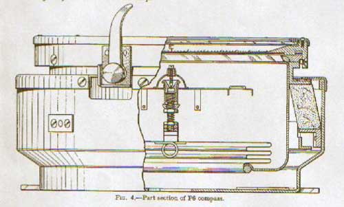


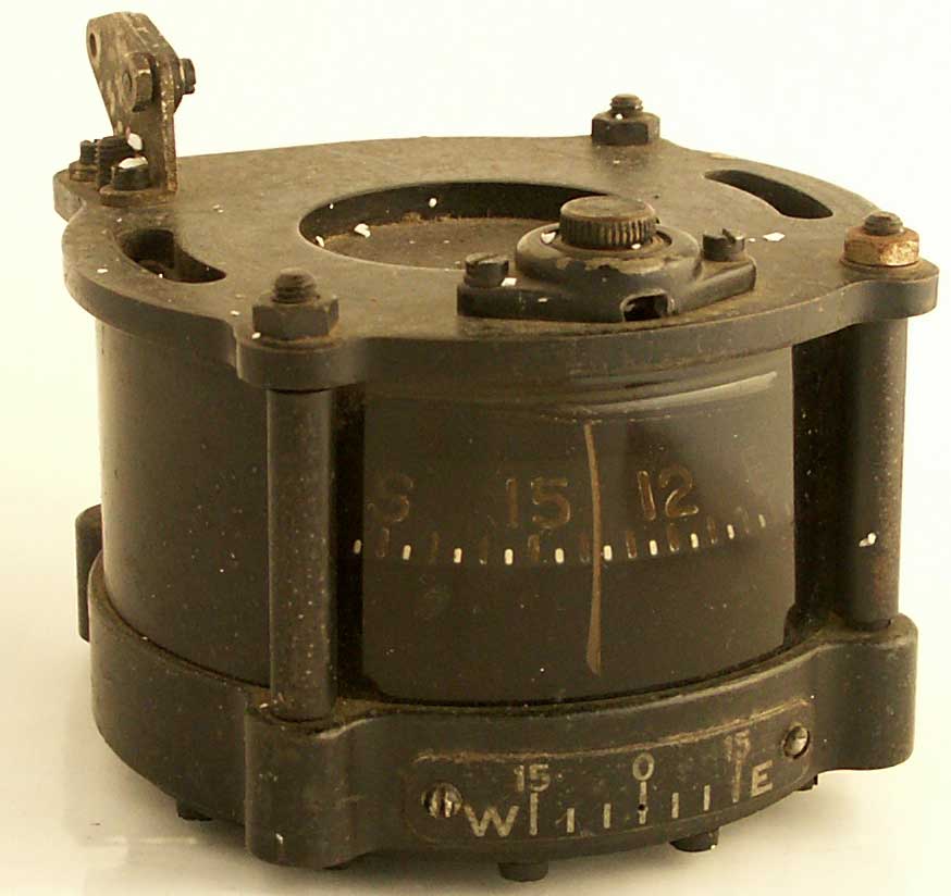


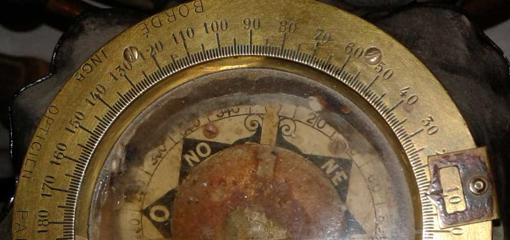


